-
../../index.html: emC overview page
-
../../../smlk/Download/Smlk_TestOrthBandpass_2021-08-15.zip: Example to test
-
../../../emc/deploy/src_emC-2021-08-14-source.zip: Used sources
-
https://github.com/JzHartmut: Archive of emC
-
../../../smlk/index.html: Simulink stuff
-
../../../StimuliSel/html/StimuliSel.html: It is used here, see example
1. Approach
A bandpass filters a signal by frequency, see for example https://en.wikipedia.org/wiki/Band-pass_filter.
The here presented bandpass outputs two orthogonal values, which is the complex representation of the two states of the filter. The complex representation allows for example a calculated phase shifting via vector rotator. The input of the bandpass can be either a single signal or also a complex value.
The bandpass is able to control in its band width. A widely band calculates also exact orthogonal components. With such an solution changes in magnitude and phase on a given frequency can be fastly detected, also in only a part of a period.
2. application possibilities
In the electrical grid and motor control the control of the basic values uses the field oriented control. For that the oscillating input values for current and voltage are transformed to direct values (https://en.wikipedia.org/wiki/Direct-quadrature-zero_transformation, also named Park-transformation) and the control used direct values. It is some more simple. Some filters can be given as simple smoothing blocks.
In opposite this filter works on the not transformed frequencies. Also filter for harmonics can use this approach. For example oscillating higher frequently cable resonances can be detected, filtered and suppressed.
Some other applications also in mechanical oscillating systems are possible.
This orthogonal bandpass filter is given as C/++ module in the emC library pool as well as also as Simulink SFunction blocks. It can be also available for Modelica. For that it can be used in simulations too.
3. application examples
3.1. A filter for a constant frequency
This is the same as, for example, an L-C resonant circuit for a AM broadcast receiver. The filter is tuned for a specific frequency, and this frequency is accepted.
The following example shows a simulation which is not for AM broadcast, but for 50 Hz oscillation to detect the frequency. The calculation time (may be in an embedded application) is 50 µs, hence a period of the frequency has 400 sampling points (20 ms / 50 µs). The input is a frequency which turns from 49.0 Hz to 51.0 Hz. The curve shows in the 3. track especially the phase difference between the input and the real output. This phase difference is zero if the input has exactly the resonance frequency. In the range of band width it goes from -45° to +45°. Hence the frequency difference to the resonance is detectable with the direct given phase signal. This is the same as the effect of a FM demodulator in a broadcast receiver.
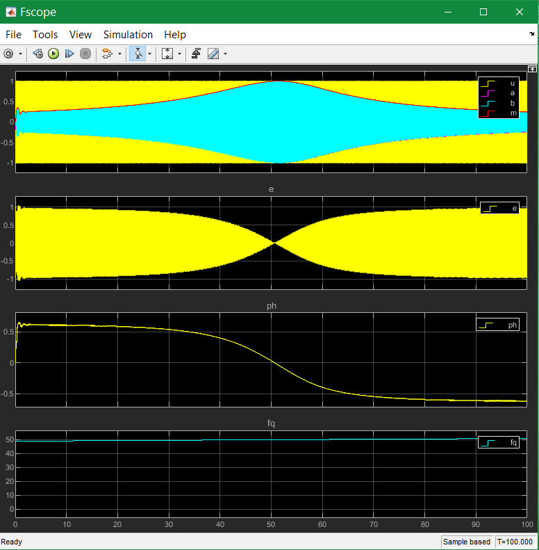
Between 49.9 and 50.1 Hz the phase in Track 3 is linear, that is approximately the band width with 0.7 (3 dB) damping on its borders. In this range the frequency is able to measure immediately by evaluation of the phase.
The model for this simulation run is the following:

The Orthogonal Bandpass is contained in the Subsystem, chapter Sfunction or Simulink. The xbdiff is not used, it’s zero. Building the difference is done only from the a output component. The phase is detected by rectifying the error value (the difference between input and output) with the sign of the imagine component. The following average filter smoothes the value as shown in the scope.
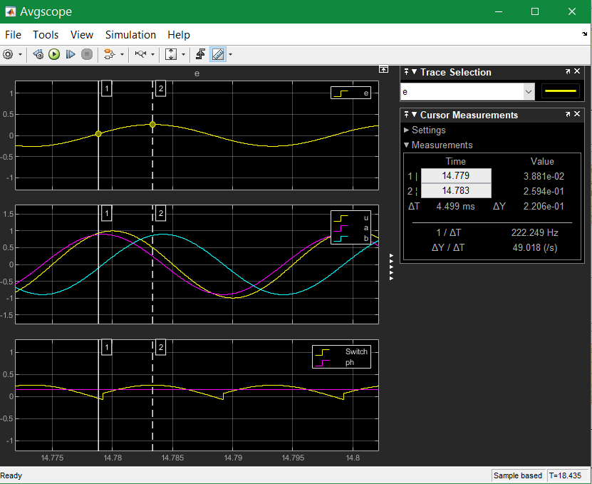
The middle track shows yellow - the input signal u. The red a component should exactly follow the input - but only on exactly the resonance frequency. A little bit outside the resonance it does not follow exactly, with the given magnitude and phase error.
The cyan signal is the imagine component, exactly 90° related to a with the same magnitude though the resonance frequency is not reached. That is an important property of the filter.
The first track is the error signal, this is the difference between yellow and red in the second track. If the phase difference is at maximum, this signal is at maximum (cursor 2). But the signal is of course 0-symmetrical. The other half wave is the same with other sign.
Now the imagine component is used to decide the sign and switch the error signal. It is similar as rectify an alternate current. But the information for switch comes from that signal which is 90° related and hence sensitive for the phase difference. The rectified error signal is shown in the 3rd track. This is averaged after them.
Hence the value for the phase depends on the magnitude of the signal. On normalized inputs it can be used immediately as information for the angle for example for AFC (automatic frequency control).
3.2. Swing on and swing off
For some filter applications with dynamic signals a fast swing on, off and change swinging on different magnitude and phase values of the input signal is necessary.
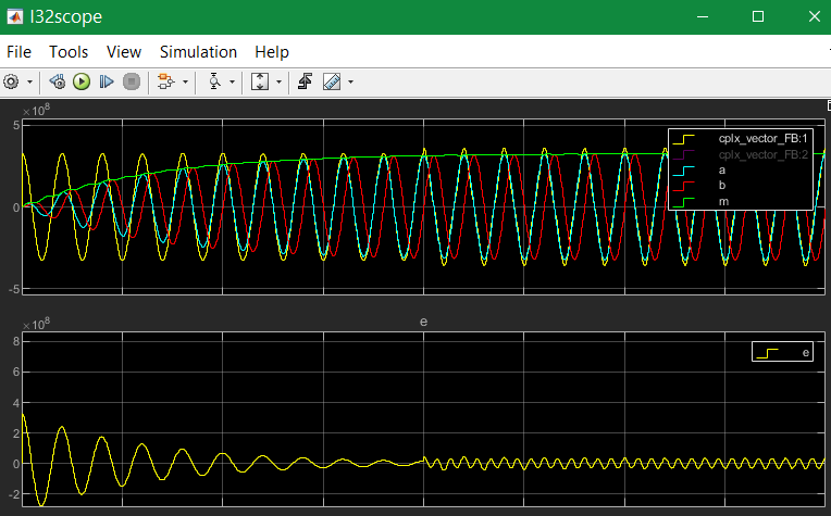
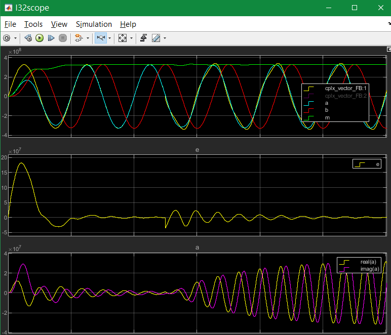
The swing on for a lesser input coupling (kA = 0.1) looks as following:
 .
.
It needs ~ 10 or more periods to follow the input signal. In this example after the 10th period a 3th harmonic is added. You see a little step, and more pointed waves for the yellow input as result with the 3th harmonic. But the swinging signal or the OrthBandpass is not changed. The harmonic is seen in the error signal in the 2th track. On the left side of this track you can see the transient, as error value. This is detached from the error by the harmonic.
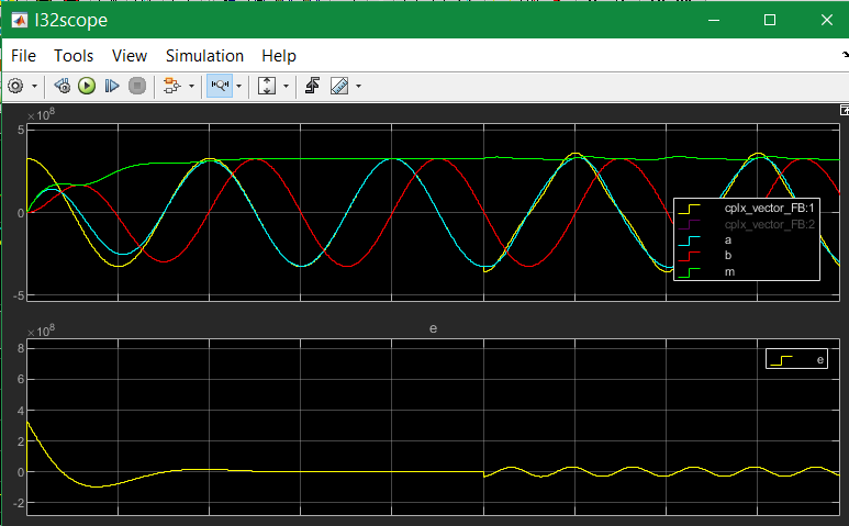
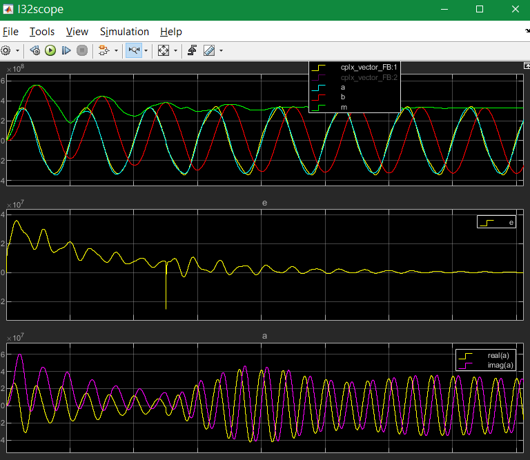
If the input coupling is far, kA=1.0 it looks like following:
 .
.
After already one period the band pass has the correct oscillation, with both orthogonal valued, with only one input signal. The 3th harmonics is added. Then you will see a bit of unrest in the amplitude (green). It means the oscillation of the band pass contains a part of the 3th harmonics. This is not seen with the k=0.1 coupling. But a larger part of the 3. harmonics remains in the error value, it is not gripped.
Is it possible to do more faster? See next:

This is for input coupling factor 10.0. It means the difference (error value) is multiplied with 10.0, it forces following. Also the imagine component follows as integral of the a component.
But what’s happen with another start phase:
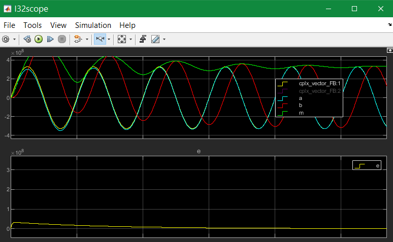
The a component is ok because of the strong input coupling, but the imagine component is firstly integrated in a faulty way, only after ~4..5 periods it is okay. This is usually not useable, for example to get an currently angle in post processing.
Hence the whole solution is not useable. Starting with the cos-step is only a special, a best case. Starting with the sin-increasing is the other special, worse case.
If the input signal comes with two components, it is better. For this example the second component is built by derivation of the input signal. Deviating a sin results in cos, the -cos is proper as second input. This is because in the input signal both informations are contained: A value itself and the derivation (change of the value in time). If you stay on a street crossing with a car, yield, you see another car comming for only .. 1 second and you can estimate its location (meter from the crossing) and also its estimated velocity. Then you decide with knowledge of this two values and you know what’s happen in the future. If the other car is near and slow, you can drive.
The following image shows the result for using the derivation:
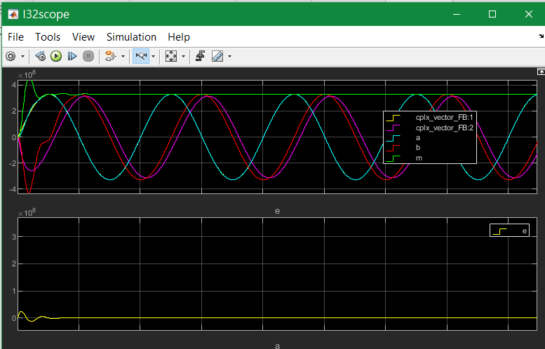
But the derivation is build not only simple. If you have some disturbance or harmonics in the input signal, the derivation should be combined with a smoothing. You see on the image above the deviated input signal with smoothing in pink, the oscillating imagine component is red. Both have an angle difference, and also a small magnitued difference, because the smoothing.
For comparison the smoothing is also regard in the feedback:
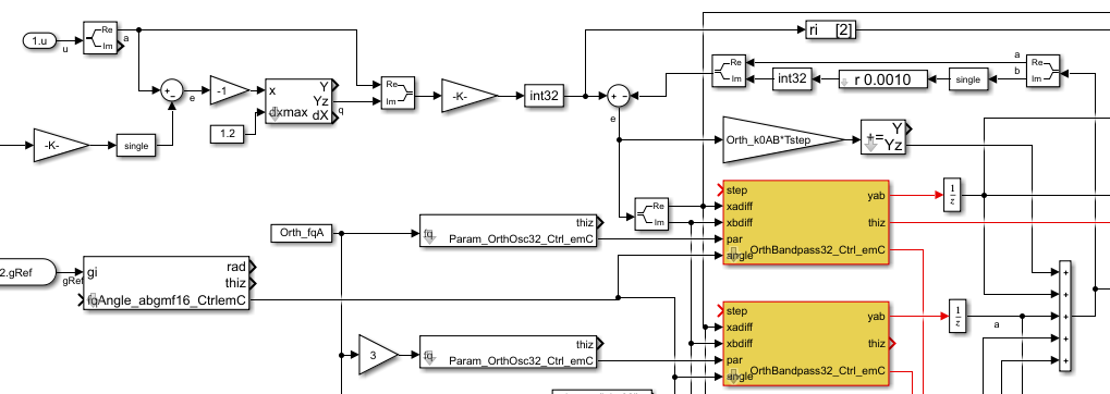
The derivation is built with a smoothing time of 1 ms. But also the feedback value is smoothed with the same value. Hence both are comparable, and the result influences the imagine component. The smoothing is less enough to built a proper error signal, and it is great enough to suppress noise.
Look into the derivation builder:

You see the core derivation, the difference of two step times multiplied with the factor (Ts/Tstep) left side.
Then the derivated value is limited, because it should be always in a defined range for sinusoidal values. On step inputs it is high, and limited because the derivation of a step is not sensitive. After limitation there is the smoothing block. The smoothed signal is usable.
The same smoothing is contained in the FBlock [r 0.0010] in the feedback, image two times above.
3.3. Division of harmonic and other frequency parts
In comparison with the chapter and image above, this scope shows the outputs with detection of the 3th harmonics:
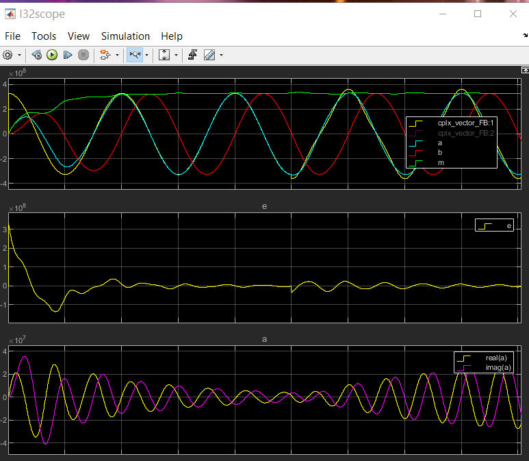
As you see, the amplitude (green track 1) is smoother. This is because the 3th harmonics is detected and subtract from the error value, see track 2. At the beginning of track 2 the error is even more erratic because the band pass for the 3th harmonics starts oscillation from the beginning step of the input signal and disturbs the detection of the pure 1th harmonics. The 3th harmonics is not contained in the input signal, but the first step contains it. If you see in the track 3, the proportion of inappropriate 3rd harmonics decreases till zero. But if the 3th harmonic occurs in the input signal, then it increases again and cleans the error value.
The following schematic shows how the harmonics can be filtered:
The blue lines and sum is the feedback from the outputs of more band pass modules.
The sum is subtract from the input signal, and the difference influences with the same
all OrthBandPass modules. The modules are tuned on the different frequencies.
You see left side per OrthBandpass module a Param_OrthBandpass32_emC_Ctr module.
This modules prepare the parameter for each band pass. Any band pass module pick up
it’s useable part from the error signal.
Then it oscillates with its own frequency if the error signal contains such one stimulation.
That decreases the error signal.
The OrthBandpass32_emC_Ctrl modules oscillate furthermore if the error is exactly zero,
with the given magnitue and phase.
As long as the sum matches the input signal, the error remains 0 and everything is stable.
If the input signal changes, an error signal is output and the corresponding bandpass
changes its behavior due to the error until everything is in balance again.
It may be interesting what’s happen with the harmonics if the signal does not start with a step to 1.0 (cos), instead start with increasing (sin):
The 3th harmonics is detected too in the start of the signal, but lesser. It depends on the containment of the error signal, which is errorneous on beginning because the whole filter is not working in its feedback on start. The filter’s a component comes delayed because it depends also on the imagine component.
If the input coupling is very strong (kA=10.0), and also the input coupling for the harmonics is strong (kA3=1.0), the behavior for the same input is the following:
You see that the real component follows immediately the input, the imagine is faulty on beginning. If the harmonics comes, firstly the real output follows. But after 1..3 periods the band pass for the 3th harmonics take over, hence the real output (cyan in track 1) is clean. Look for detail view:

The differences may be important on post processing of the filtered signals.
Let’s have a look on the filtering of the input signal with its derivation.
The input coupling factor is 2.0. On 10.0 it is worse. An important trick: The detected harmonic is subtract from the input signal before derivation. Hence the input before derivation is more sinusoidal, and the derivation does not contain to high harmonics. Note that in the derivation the harmonics are overemphasized.
The solution in the model is:

Shown with the blue lines the detected 3th harmonic is subtract.
3.4. Using for detection of high frequencies in the signal
In the image above in the chapter before you see that there can be more parallel OrthBandpass modules, using the same error signal and adding there outputs. In that kind all known harmonics and maybe other frequency parts, for example also the carrier frequency of a converter can be filtered.
Some times a signal is disturbed by oscillations from other reasons. In mechanical systems these can be any vibrating mechanical parts (spring and mass). In electrical grids the lines with its inductances and capacitances has resonances. This resonances are often in ranges of 500 Hz .. some kHz. This is then the remaining error if all other components are filtered.
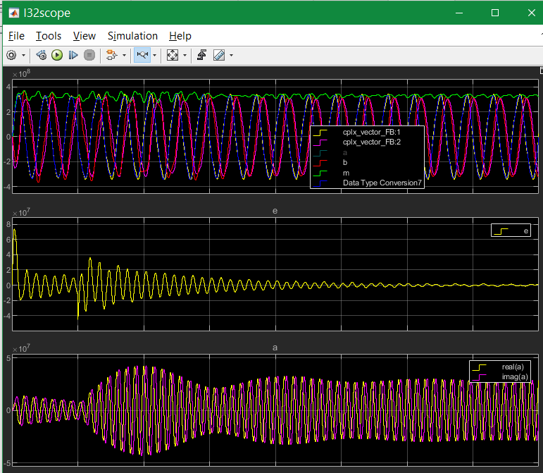
The OrthBandpass can be used for frequencies which are near the step solution, till 6..5 values per period. The next images shows results:

The result for the shown values is:
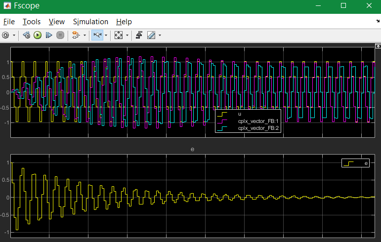
In this case the Tstep is 50 µs, it means with 3.33 kHz is ~ 6 samples per period as seen.
But what about a fractional number of samples, tested with 3.5 kHz:
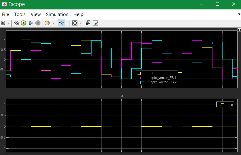
The swing on looks like the image above. This is a zoom after swing on. You see that each period has its own value, and the a and imagine component follows exactly if it is settled.
Now you have a pair of values, a vector, which represents the high frequency oscillation, and this vector can be used for outputs to supress the oscillation.
4. Equations of the OrthBandpass
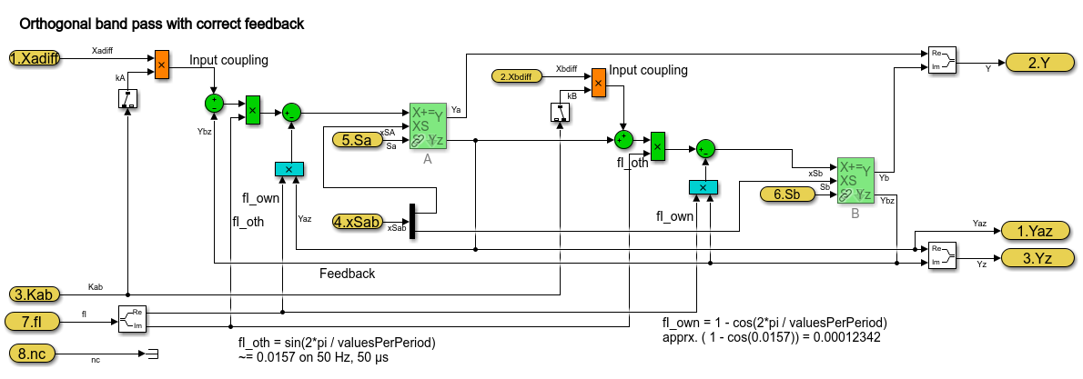
The pure Simulink model for an orthogonal band pass looks like:
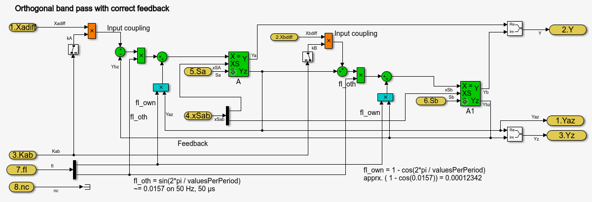
The green blocks are the feedback between the both components. The other component grows per step time with a factor ~0.0157 for 400 steps per period. This is only an example value. The OrthBandpass works also with down to 6 steps per period. Then this factor is ~ 0.866.
The [X+=] Fblocks are the integrator in the step time.
The blue blocks describe the correction of the own value per step. A little part is subtract from the pure integration (Factor 0.00012 for 400 steps per period). For 6 steps per period this is 0.5. It means only the half value remains.
The orange blocks are the influence of the input (error value) to the oscillating values.
This equations are the same as the solving of differential equations for a L-C band pass:
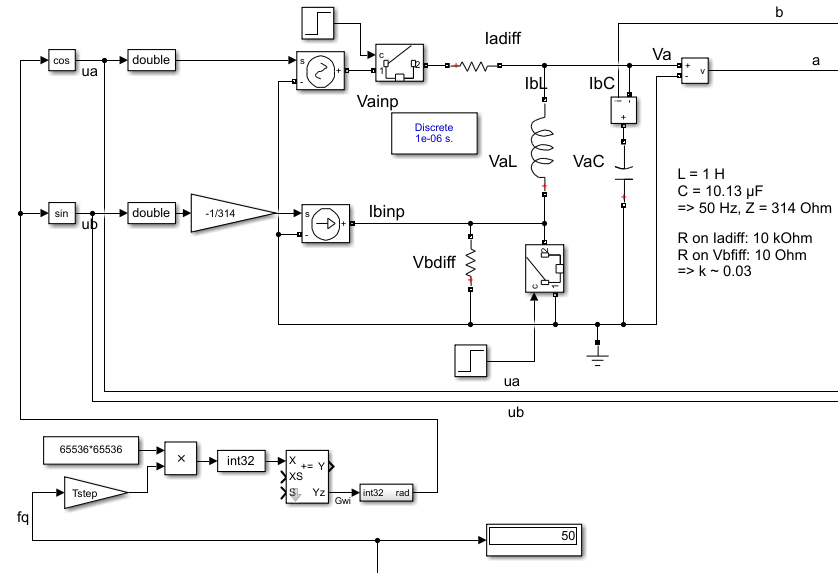
Basic differential equations for L and C
-
1)
duC/dt = iC / C; -
2)
diL/dt = uL / L ;
Application to the schema names:
-
1)
dVaC/dt = IbC / C ; -
2)
dIbL/dt = VaL/L ;
Including inputs. Due to the algorithm of the OrthBandpass module the input is the difference value, adequate here Iadiff and Vbdiff. Building if the differences is outside.
-
1)
dVaC/dt = (IbL - Iadiff) / C ; -
2)
dIbL/dt = (VaC - Vbdiff) / L ;
The state values are Va = VaC (the real component) and Ib = IbL (the imagine component). To get this the both equations should be written as integral, it is the solution for the differential equations in the time.
-
1)
Va = ∫ (Ib - Iadiff) / C ) dt; -
2)
Ib = ∫ (Va - Vbdiff) / L ) dt;
For the stepping system dt is the step time (Tstep).
For a simple solution the growth in the step time is 1/L * Tstep instead 1/L dt
and adequate 1/C* Tstep.
For the numeric solution the values of L in Vs/A and C in As/V are replaced by simple constants
without units. The factors are related to an impedance Z=1 Ohm for L and C.
So the units are removed.
The factors 1/L * Tstep and 1/C * Tstep are then equal, named fI_oth.
It is the integration factor caused from the other component.
Then a simple integration of one component with the other component with the given factor results:
Hint: a is the variable for the real component, b is the imagine one.
-
1) a += fI_oth * b ;
-
2) b += fI_oth * a ;`
But: For a more exact behavior in longer step times in comparison to the period
it should be regarded that it is not a simple integration of one component with the other.
In comparison with infinite short time the component itself is already changed
to the next time step Tstep.
The solution of the differential equation is a sin and cosin oscillation, as known. It means, in the Tstep time the own component is changed really by a little value, which is part of a cos. - And the growth from the other component is not linear but a sin. Following the integration is done with:
-
1) a += fI_oth * b - fI_own * a ;
-
2) b += fI_oth * a - fI_own * b ;`
It means the correction of the own component as effect inside the Tstep step time is done with the factor fI_own. The both factors are calculated with the relation of the resonance frequency and the step time:
-
rad = 2π * fq * Tstep ; //growth per step time in radiant
-
fI_own = 1 - cos(rad) ;
-
fI_oth = sind(rad) ;
For many steps per period the fI_own is near zero, so that this part can be dismissed if the accuracy is lesser, for example for fast calculation in 16 bit arithmetic and a strong coupling (k~ >=0.1) for the inputs. But especially if the Orthogonal band pass is used for high frequencies (for example for oscillation detection on electrical lines) with the fI_own correcture it works accuracy, as shown in chapter Using for detection of high frequencies in the signal.
5. Implementing in C, SFunctions for Simulink and quest of accuracy
If double arithmetic is used, the results should be accuracy. But double arithmetic is often not available in embedded processors as built-in in hardware. It is only available with higher calculation time effort in double arithmetic libraries. The first question is: Is this accuracy necessary? Often the answer is "no".
Then the next approach is float arithmetic. Powerful embedded processors have often a float hardware support. The accuracy may be ok in practice.
Float arithmetic has a mantissa length of 24 bit. The hardware arithmetic in controllers supports normally 32 bit addition and multiply, often 32 bit to 64 bit multiply with an option to use only the low- or high 32 bit part of the result. This forces thinking about 32 bit integer arithmetic. It has a higher resolution, 32 against 24 bit. But it is fix.
The world is also fix. In typical technical applications inputs come from measurement with 12…16 bit resolution. Actuators works with 8..16 bit. The higher resolution of 32 bit is nice to have and necessary for intermediate results and state values. Especially states and differences of states and inputs need this higher resolution. Hence pure 16 bit integer arithmetic is usual to less, only for simple applications running on simple controllers.
Now it is a decision - using float with 24 bit resolution but well scaled numbers or using integer with 32 bit resolution but often not really used. The problem is that an overdrive also for intermediate results is necessary. Hence often only 30..31 bit are useable for the application (range till max 0x40000000, not till the theoretical 0x7fffffff because overflow regarding).
The OrthBandpass is a good example for this general question. For that it is realized in float, int32 and int16.
For all three resolutions the core algorithm in C, adapt also to C++ usage are available. With this core algorithm and the vishia-SFunction generator for Simulink proper SFunctions are built as also seen in the examples.
5.1. Sfunction or Simulink
The next image shows usage of the OrthBandpassF module as Simulink module and as S-Functions:
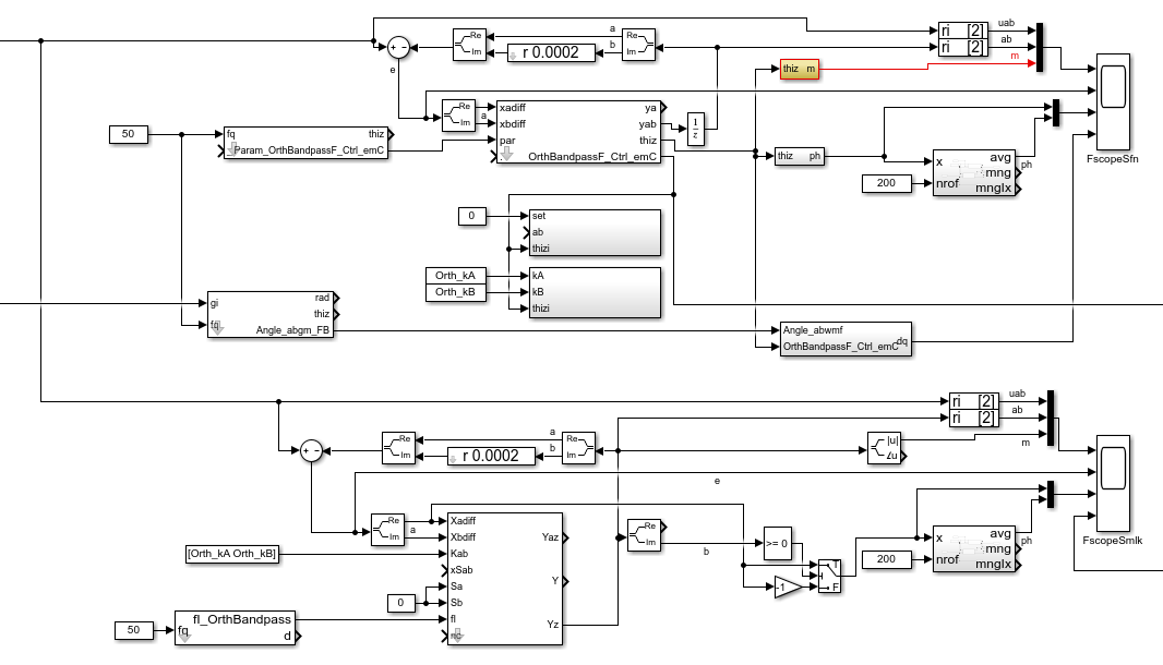
The top half shows the S-Function usage, the botton half uses the Simulink module. The functionality is usual similar. For the SFunction solution additional a park transformation (built direct representation values dq from rotating ones) in an ObjectOriented form is adding. This is in Simulink a vector rotator, not shown here.
The SFunctions are Object oriented. It means to get the magnitude an access to the whole data
named “thiz” is used. With this solution a faster algorithm as the sqrt() for the magnitude
is used, which needs stored values in the class Data of the OrthBandpassF_Ctrl_emC.
The same solution drawn as Simulink FBlocks may be a little bit complicated
because of the necessary access to stored values.
As SFunction it is only a simple SFBlock with thiz handle.
The internals are hidden in C, a black (gray) box principle.
The adequate is seen also to build the phase information.
The both SFunctions with set - a b and kA kB are not used in this model, only presented.
It is adequate the Kab, xSab, Sa and Sb inputs from the Simulink module.
With that it is possible to change the input coupling for example on input signal quality changes
and to set the current values, a functionality for special situations.
This SFBlocks are so named "Operation FBlocks",
operations to the Object Fblock OrthBandpassF_Ctrl_emC which holds the data.
They can be used if necessary. Same is with the FBlocks [thiz m] and [thiz ph]
which accesses and calculates values of the Object-FBlock.
The model in the botton half is shown in chapter Equations of the OrthBandpass
5.2. Floating point solution in C
This is the base of the SFunction.
Parameter data:
typedef struct Param_OrthBandpassF_Ctrl_emC_T
{
  ObjectJc obj;

  /**Frequency and step time. */
  float tStepOrthi;

  /**The given frequency in step routine. Only for debug. 0.0 if nStepPeriod is given. */
  float fq;

  /**The given steps per period in step routine. Only for debug. 0.0 if fq is given. */
  float nStepsPeriod;

  /**Factor for magnitued regards the nominal value.
   * It is 1/m_nom/2.
   */
  float fm;


  /**Integrator factor from the other component.*/
  float fI_oth;

  /**Adjust for the own component in one step time. Less, ~ 0.00... */
  float fI_own;

} Param_OrthBandpassF_Ctrl_emC_s;
This are the parameter values, able to use for more as one OrthBandpass module
which should filter the same frequency.
Some values are especially for debugging. The fq and nStepsPeriod are given
by input operations, and manifested in fI_own and fI_oth for calculation.
This values are not necessary for the calculation itself but maybe interesting
for debug approaches in the C/++ solution.
The fm is a factor for building the magnitude.
The struct is based on ObjectJc. At least that is necessary for the SFunctions. See also ../Base/ObjectJc_en.html.
/**
 * @simulink Object-FB.
 */
static inline void setFq_Param_OrthBandpassF_Ctrl_emC ( Param_OrthBandpassF_Ctrl_emC_s* thiz,
                                                        float fq)
{
  float fI1 = 2*PI_float_emC * thiz->tStepOrthi * fq;
  thiz->fI_own = 1.0f - cosf(fI1); //the little rest to subtract
  thiz->fI_oth = sinf(fI1);    //forward gain from other compn, determines fq
  thiz->fq = fq;
  thiz->nStepsPeriod = 1.0f / (fq * thiz->tStepOrthi);
}
This is the calculation of the factors for a given frequency. It does not should and need be called in a fast step time, because longer operations for sin(), cos() and division. The division is only necessary for debugging approaches. It may be set under conditional compilation.
Working data:
/**Internal data of a Orthogonal Bandpass.
 * @simulink no-bus
 */
typedef struct OrthBandpassF_Ctrl_emC_T
{
  ObjectJc obj;  //:The base structure
  Param_OrthBandpassF_Ctrl_emC_s* par;  //:Reference to parameter, maybe calculated in other step time.

  /**Input coupling factors. Note: kB should be negative for same difference B-X, A-X*/
  float kA, kB;

  /**Stored values on step for evaluation. */
  float xadiff;

  float m;        //:optional: Magnitude and its reciproke, if calculated

  float_complex yab;  //:Orthogonal components of oscillation.

} OrthBandpassF_Ctrl_emC_s;
The parameter are referenced here for working. It is an aggregation in terms of UML.
The input coupling factors kA and kB are instance-specific, because some OrthBandpass with the same frequency and hence parameter can have different filter necessities.
The xadiff value from the input is stored for calculation a phase representing value.
The m magnitude is the stored value from the last calculation for an iterativ algorithm.
The core step algorithm for filtering:
/**Step routine. It calulates the stored values of Orthogonal Oscillation.
 * @param xAdiff Difference between Input and yab.re Signal
 * @param xBdiff 0 for only single input, or orthogonal difference from the other component
 */
static inline void step_OrthBandpassF_Ctrl_emC(OrthBandpassF_Ctrl_emC_s* thiz, float xAdiff, float xBdiff)
  {
#ifndef __ignoreInCheader_zbnf__
  Param_OrthBandpassF_Ctrl_emC_s* par = thiz->par;
  thiz->xadiff = xAdiff; //store for evaluating (phase) and debug view
  float a = thiz->yab.re;
  thiz->yab.re -= par->fI_own * thiz->yab.re;
  thiz->yab.re += par->fI_oth * ( thiz->kA * xAdiff - thiz->yab.im);
  thiz->yab.im -= par->fI_own * thiz->yab.im;
  thiz->yab.im += par->fI_oth * ( thiz->kB * xBdiff + a);
#endif//__ignoreInCheader_zbnf__
}
In C language it is more simple as in Simulink.
Writing with += lies close for using a "multiply and add" statement
which is available on the machine statement set of some signal processors.
Only a hint: The #ifndef ignoreInCheader_zbnf_ is only for the parser (ZBNF) for reflection,
should not parse this parts. It is nonsense for the C/++ compilation.
Building the magnitued:
Using the pythagoras algorithm needs a sqrt function. Yet, implementing more complex functions on cheap processors need calculation time. The sqrt may not be far complicated, but if it is possible to replace it without disadvantage, it can be done.
/**Calculates the magnitude in an iteration algorithm.
 * Each step time is one iteration.
 * The input values are usual not far changed from one to the next step time.
 * @simulink Operation-FB, accel-tlc.
 */
static inline void calcMagn_OrthBandpassF_Ctrl_emC(OrthBandpassF_Ctrl_emC_s* thiz, float* m_y)
{
#ifndef __ignoreInCheader_zbnf__
  //firstly calculate a estimation for the magnitude.
  //The real value is between this and 1.0 of the sum. It means it has an error from max. -30%
  //but this value is lesser than the real magnitude.
  float fm = thiz->par->fm;
  float mx = (fabsf(thiz->yab.re) + fabsf(thiz->yab.im)) * 0.707f;
  float dmx = mx - thiz->m;
  if( (thiz->m * fm ) > 1.5f || fabsf(dmx) > thiz->m) {  //the difference is high in comparison to the magnitude,
    //then do not iterate. It may be infinite.
    thiz->m = mx;    //use the estimation.
  }
  else {   //the difference is < 0.5 * magnitude, then it is possible to iterate:
    //divide by 2 is the nearest approximation for change, it regards the fact
    //the derivation of sqrt is 1/2*x. Adding the derivation.
    float m2 = (thiz->m * thiz->m);
    float ab2 = ((thiz->yab.re * thiz->yab.re) + (thiz->yab.im * thiz->yab.im));
    float dm = fm * (ab2 - m2);
    thiz->m += dm;
  }
  *m_y = thiz->m;
#endif//__ignoreInCheader_zbnf__
}
The idea is, that the difference from the last calculated magnitude to the new value is less. Calculating the difference in the quadratic coordinates does not need a sqrt and doesn’t also need a division. But this algorithm has a potential quadratic growing feedback on large values. Hence generally it works only for a deterministic range. But this is proper for technical systems.
Firstly a magnitude is estimated, with an error till -30%. With this estimation it is tested whether the stored magnitude is near (30%) the expected value. It is not so, or the magnitude is too high (cannot work), then the estimation is used. It is a start value, lesser as the real expected magnitude with this possible error of 30% from the exact value.
If the stored magnitude from the step time before is proper, an exact calculation is done.
The difference dm is controlled to zero, by comparison of the quadratic sum of the components
and the quadratic stored magnitude. If dm is zero, the magnitude thiz-m is exact and not changed.
If dm is less, the magnitued is tuned. Whereby for a magnitude value exact of m_nom,
the given nominal value in constructor, the correction is exact.
This is because the derivation of sqrt(x) is is x/2 and the factor fm is set in this kind.
For higher values of the magnitude it is over-corrected.
If the magnitude will be >= 2.0* m_nom it would oscillate. Hence this range is forbidden.
For for lesser values it is to less corrected.
Hence on low magnitudes the correction is slow. It is similar a smoothing effect,
which is also often desired. Smoothing effects are also part of the filter anyway.
This magnitude building algorithm can be used for some approaches. But it is not an universal solution. On unknown relations or not smoothed calculation requirements use the pythagoras with sqrt().
5.3. int32 solution in C
Using int32 instead float has two advantages:
-
Maybe the controller has no floating point support
-
The resolution is higher because 32 bit instead 24 bit for the mantissa are useable. But because the range is fix, usual only 30..31 bit are effective. But it is more than 24.
Hence the int32 solution may also be interesting in floating point environments Some parameter data are given in float, and a calculation is done maybe in double. It means if the controller has not floating and double hardware support, a float and maybe double library is necessary to calculate correct parameter values. But in the fast step time only int32 is used.
This is the base of the SFunction.
Parameter data:
/**Parameter set for int32 Orthogonal band pass
 * @simulink no-bus
 */
typedef struct Param_OrthBandpass32_Ctrl_emC_T
{
  ObjectJc obj;

  /**Frquency and step time. */
  float tStepOrthi;

  /**The given frequency in step routine. Only for debug. 0.0 if nStepPeriod is given. */
  float fq;

  /**The given steps per period in step routine. Only for debug. 0.0 if fq is given. */
  float nStepsPeriod;

  float _align8;

  /**Integrator values form same signal, from other.*/
  int32 fIcos, fIsin;

} Param_OrthBandpass32_Ctrl_emC_s;
It is similar the float solution. The fm factor for the magnitude is not necessary because the range is intrinsic nominal .
void setFq_Param_OrthBandpass32_Ctrl_emC(Param_OrthBandpass32_Ctrl_emC_s* thiz, float fq)
{
  thiz->fq = fq;
  #ifdef USE_float_OrthBandpass32_Ctrl_emC
    float fI1 = 2*PI_float_emC * thiz->tStepOrthi * fq;  //rad of 1 Tstep
    float fI_oth = sinf(fI1) * 1.00000f;
    int32 fI_oth32 = (int32)(65536.0f * 65536 * fI_oth + 0.5f);
    float fI_own = 1.0 - cosf(dI1);
    int32 fI_own32 = (int32)(-65536.0f * 65536 * (fI_own) - 0.5f);
  #else
    double fI1 = 2*PI_emC * thiz->tStepOrthi * fq;  //rad of 1 Tstep
    double fI_oth = sin(fI1);
    int32 fI_oth32 = (int32)(65536.0 * 65536 * fI_oth + 0.5);
    double fI_own = 1.0 - cos(fI1);        //note: negative value for fI_own32
    int32 fI_own32 = (int32)(-65536.0 * 65536 * (fI_own) - 0.5);
  #endif
  thiz->fI_oth = fI_oth32;
  thiz->fI_own = fI_own32;
}
That is the implementation in the C file as content of the Simulink Object-FB. It is a little bit more complicated than the float solution:
-
It is selectable, set the compiler switch centralized in the
applstdef_emC.h, whether double is available or not. Using float the accuracy is about 2..3 bits worse. -
The factors are related to the decimal point left of the 31th bit. It is simple for multiplication. The factors are guaranteed < 0.5, Hence the sign is 0. But this limits the minimal steps per period to 6.3. For a higher value the fI_own will be >= 0.5 =^ > 0x7fffffff, and this is negative.
Working data:
/**Internal data of a OrthogonalOscillator.
 * @simulink no-bus
 */
typedef struct OrthBandpass32_Ctrl_emC_T
{
  ObjectJc obj;  //:The base structure
  Param_OrthBandpass32_Ctrl_emC_s* par;  //:Reference to parameter, maybe calculated in other step time.
  //Angle_abgmf16_Ctrl_emC* anglep;   //:Reference to angle, null is admissable.

  /**Couple factors. Note: kB should be negative for same difference B-X, A-X*/
  int32 kA, kB;

  /**Stored from input step_... for ph_ output. */
  int32 xAdiff;

  int32 m;

  int32_complex yab;    //:Orthogonal components of oscillation.

} OrthBandpass32_Ctrl_emC_s;
This is also similar the float solution. All values are int32.
Set kA and kB:
void setkAB_OrthBandpass32_Ctrl_emC(OrthBandpass32_Ctrl_emC_s* thiz, float kA, float kB){
  //max value of kA = 15.9999 is mapped to 0x7FFFFFFF, regard sign, hence sign from float
  thiz->kA = fabsf(kA) < 16.0 ? (int32)(0x08000000 * kA) : *(int32*)(&kA) | 0x7fffffff;
  thiz->kB = fabsf(kB) < 16.0 ? (int32)(0x08000000 * kB) : *(int32*)(&kB) | 0x7fffffff;
}
This routine is called on construction and in the set Operation-FB.
The values are given as float, but stored as int multiplication factor.
The decimal point is left from the bit 27, so a maximal value of float 15.999 can be used.
16.0 causes 0x80000000 which is negative and hence faulty.
The core step algorithm for filtering:
static inline void step_OrthBandpass32_Ctrl_emC ( OrthBandpass32_Ctrl_emC_s* thiz
                                                , int32 xAdiff, int32 xBdiff)
{
#ifndef __ignoreInCheader_zbnf__
  Param_OrthBandpass32_Ctrl_emC_s* par = thiz->par;
  int32 ad;
  thiz->xAdiff = xAdiff;
  muls32hi_emC(ad, thiz->kA, xAdiff);  //input diff * kA
  if(ad < 0x04000000 && ad > -0x04000000) { ad <<=5; }
  else ad = ad <0 ? 0x80000000 : 0x7fffffff;  //limit it if too large.
  ad -= thiz->yab.im;                   // - other comp (im)
  muls32hi_emC(ad, ad, par->fI_oth);    // increment of own comp (re) from adiff and im
  muls32addhi_emC(ad, thiz->yab.re, (par->fI_own));    //sub the little bit for stability
  int32 a = thiz->yab.re;
  thiz->yab.re += ad;
  //
  int32 bd;
  muls32hi_emC(bd, thiz->kB, xBdiff);   // input diff * kA
  if(bd < 0x04000000 && bd > -0x04000000) { bd <<=5; }
  else bd = bd <0 ? 0x80000000 : 0x7fffffff;  //limit it if too large.
  bd += a;                              // + other comp (re)
  muls32hi_emC(bd, bd, par->fI_oth);    // increment of own comp (re) from adiff and im
  muls32addhi_emC(bd, thiz->yab.im, (par->fI_own));    //sub the little bit for stability
  thiz->yab.im += bd;
#endif//__ignoreInCheader_zbnf__
}
Here the first problematic is: multiply an input difference xAdiff and xBdiff with kA and kB.
-
The input difference can be in range -0x80000000 .. 0x7fffffff, the full range.
-
Multiplying with kA and kB needs shift to 5 bits because the decimal point for kA and kB is left of bit27.
-
But shifting may be cause an overflow if the difference is high and kA, kB is >1.0. Hence a test is necessary. Shifting is only done if no overflow occurs. If an overflow may be occure, the maximum is used.
The multiplications are done with the approach 32 bit * 32 bit results in 32 bit high part. This is optimized for 32 bit processors. To support this statements the macros are used see Fixpoint_float.html.
5.4. int16 solution in C
The int16 solution does also use float arithmetic parts for parametrizing. The accuracy is enough if the filter is not too less in band width.
Parameter data:
/**Parameter set for int16 Orthogonal oscillator
 * @simulink no-bus
 */
typedef struct Param_OrthBandpass16_Ctrl_emC_T
{
  ObjectJc obj;

  /**Frquency and step time. */
  float tStepOrthi;

  /**The given steps per period in step routine. Only for debug.  */
  float nStepsPeriod;

  /**Integrator values form same signal, from other.*/
  uint16 fI_own, fI_oth;


} Param_OrthBandpass16_Ctrl_emC_s;
The difference to the int32 solution: The factors for integration are only 16 bit width.
/**
 * @simulink Object-FB
 */
static inline void setFq_Param_OrthBandpass16_Ctrl_emC(Param_OrthBandpass16_Ctrl_emC_s* thiz, float fq)
{
#ifndef __ignoreInCheader_zbnf__
  thiz->nStepsPeriod = 1.0f / (fq * thiz->tStepOrthi);
  float fI1 = 2*PI_float_emC * thiz->tStepOrthi * fq;  //rad of 1 Tstep
  //this value should be so exact as possible for feedback, sum of gain = 1.0,
  float fI_own = cosf(fI1);       //hence using float. cos16_emC is inaccurate.
  float fI_oth = sinf(fI1);
  thiz->fI_oth = (uint16)(65536 * fI_oth);
  thiz->fI_own = (uint16)(-65536 * (1.0f - fI_own));  //Note: negative because subtract
#endif//__ignoreInCheader_zbnf__
}
For this solution some experience were done using fix point sin and cos. But this is to inaccuracy. Because also floating point values and multiplication is necessary, also the sin is used as floating point. This routine doesn’t may be executed in a fast step time.
But for given frequencies only the pre-calculated values can be used without this function. Maybe let the compiler calculate the float values, and the machine code uses only pre-calculated int16 values.
Working data:
/**Internal data of a OrthogonalOscillator.
 * @simulink no-bus
 */
typedef struct OrthBandpass16_Ctrl_emC_T
{
  ObjectJc obj;  //:The base structure
  Param_OrthBandpass16_Ctrl_emC_s* par;  //:Reference to parameter, maybe calculated in other step time.

  /**Couple factors. Note: kB should be negative for same difference B-X, A-X*/
  int16 kA, kB;

  int32_complex yab;    //:Orthogonal components of oscillation.
} OrthBandpass16_Ctrl_emC_s;
This is also similar the float solution. All values are int32.
Set kA and kB:
void setkAB_OrthBandpass16_Ctrl_emC ( OrthBandpass16_Ctrl_emC_s* thiz, float kA, float kB)
{
  thiz->kA = fabsf(kA) < 8.0f ? (int16)(0x1000 * kA) : 0;
  thiz->kB = fabsf(kB) < 8.0f ? (int16)(0x1000 * kB) : 0;
}
This routine is called on construction and in the set Operation-FB.
The values are given as float, but stored as int multiplication factor.
The decimal point is left from the bit 11, so a maximal value of float 7.999 can be used.
8.0 causes 0x80000000 which is negative and hence faulty.
The core step algorithm for filtering:
/**Step routine. It calulates the stored values of Orthogonal Oscillation.
 * @param xAdiff Difference between Input and yaz_y Signal
 * @param xBdiff same as xAdiff for only single input, or orthogonal difference
 */
static inline void step_OrthBandpass16_Ctrl_emC(OrthBandpass16_Ctrl_emC_s* thiz, int16 xAdiff, int16 xBdiff)
  {
#ifndef __ignoreInCheader_zbnf__
  Param_OrthBandpass16_Ctrl_emC_s* par = thiz->par;
  int32 ad;
  muls16_emC(ad, thiz->kA, xAdiff);  //input diff * kA
  ad = (ad >>12) - ((thiz->yab.im>>16)&0xffff);     // - other comp (im)
  muls16_emC(ad, (int16)(ad & 0xffff), par->fI_oth);  //increment of own comp (re) from adiff and im
  muls16add32_emC(ad, ((thiz->yab.re>>16) & 0xffff), par->fI_own);    //sub the little bit for stability
  int16 a = ((thiz->yab.re>>16) & 0xffff);
  thiz->yab.re += ad; //(int16)((ad>>16) & 0xffff);
  //
  int32 bd;
  muls16_emC(bd, thiz->kB, xBdiff);  //input diff * kA
  bd = (bd >>12) + a;     // - other comp (im)
  muls16_emC(bd, (int16)(bd & 0xffff), par->fI_oth);  //increment of own comp (re) from adiff and im
  muls16add32_emC(bd, ((thiz->yab.im>>16) & 0xffff), par->fI_own);    //sub the little bit for stability
  thiz->yab.im += bd; //(int16)((bd>>16) & 0xffff);
#endif//__ignoreInCheader_zbnf__
}
The essential difference to the 32 bit solution is: only 16 bit multiplications are used.
But the result of 16 * 16 bit as 32 bit is used to integrate
with the muls16add32_emC(…) macro.
The state values are 32 bit, which is possible also on processors which have only
a 16 bit arithmetic.
The accuracy of 32 bit for using state values is necessary and a proper feature.